
Please Choose Your Language


Views: 0 Author: Site Editor Publish Time: 2026-11-20 Origin: Site


Hollow composite decking cuts down on weight and material usage, but the structural geometry requires strict adherence to specific installation parameters. Treating hollow boards like solid composite or traditional timber causes severe structural failures. You will see mid-board sagging, channel splitting, and voided manufacturer warranties if you ignore the framing rules. The internal voids reduce the sheer mass of the board. The underlying frame must compensate with precise, engineered support. This guide breaks down the exact substructure, spacing, and fastening requirements needed to execute a compliant, long-lasting Hollow Composite Decking Installation. You will learn how to engineer the subframe, manage aggressive thermal expansion, and select the correct hardware to protect the structural integrity of every board.
The longevity of Hollow Composite Decking Boards depends entirely on the airflow, stability, and regulatory compliance of the underlying frame. A deck surface is only as strong as the foundation supporting it. Failing to prepare the site correctly guarantees premature material degradation. You must evaluate the soil, plan the drainage, and build a foundation that resists frost heave and settling.
Establishing a stable base requires matching the foundation type to the soil conditions and the intended dynamic load of the deck. You must dig footings below the local frost line to prevent the structure from heaving during winter freezes. Pouring concrete directly into unlined holes often leads to shifting; use proper cardboard tube forms to create smooth, uniform piers. You must ensure the foundation connections suit the intended dynamic and static loading of the finished deck. Factor in heavy additions like hot tubs, outdoor kitchens, or large planters before pouring a single footing.
| Foundation Type | Best Application | Installation Requirements | Load Capacity |
|---|---|---|---|
| Concrete Piers | Ground-level and elevated decks on stable soil. | Must be dug below the frost line. Requires 48 hours minimum curing time. | High. Suitable for heavy static loads like hot tubs. |
| Ground Screws | Uneven terrain or areas with strict soil disturbance regulations. | Requires specialized machinery for deep driving. No curing time needed. | Medium to High. Depends on soil density and screw depth. |
| Adjustable Pedestals | Rooftop terraces, concrete balconies, or existing flat hardscapes. | Underlying waterproof membrane or concrete pad must be perfectly flat. | Medium. Best for standard foot traffic and light furniture. |
Checking local building codes is a mandatory first step. Substructures must meet legal safety and load-bearing standards dictated by regional authorities. Elevated structures often require structural engineering approval for the ledger board attachment, post sizing, and cross-bracing. Never assume standard residential framing rules apply universally. Coastal areas or high-wind zones impose stricter tie-down and uplift requirements. You must use approved structural screws and galvanized hurricane ties to secure the joists to the beams.
A minimum 25mm continuous ventilation gap beneath the decking boards is an absolute requirement. Cross-ventilation prevents localized humidity pockets that warp composite materials. Without adequate airflow, the underside of the deck absorbs rising ground moisture while the top surface bakes in direct sunlight. This severe moisture and temperature differential forces the boards to cup and bow. Ensure perimeter fascia boards do not choke off this airflow. Install ventilation grilles into the fascia if the deck design requires a closed skirt.
The sub-grade beneath the deck must slope away from the primary structure. Specify a 1% to 2% drop to prevent standing water. This equates to roughly a 10mm to 20mm drop for every meter of distance away from the house. Water pooling under the deck creates a permanent micro-climate of high humidity. This accelerates subframe rot and increases the moisture load on the composite boards above.
Composite materials suffer from thermal shock if installed immediately after delivery. Implement a 48-to-72-hour on-site acclimation period prior to cutting or fastening. Store the boards flat on the joists or on level timber bearers spaced no more than 300mm apart. Never leave the boards wrapped in tight plastic packaging in direct sunlight. The plastic creates a greenhouse effect that pre-warps the material before you even pick up a saw.
Assessing load-bearing requirements against the specific flexural strength of hollow profiles requires tighter tolerances than standard timber installations. The internal voids reduce the material's resistance to downward deflection. The subframe must do more of the heavy lifting to keep the surface flat and rigid.
The minimum joist width requirement is 38mm. This dimension provides adequate surface area to support the decking boards. It also gives the hidden fastener clips enough timber to bite into without splitting the joist edge. Treated timber joists remain the most common choice due to cost and availability. However, aluminum or composite subframes offer superior longevity. Matching the lifespan of the subframe to the decking prevents a scenario where the frame rots away while the surface boards remain intact. If using timber, apply a self-sealing butyl flashing tape over the top of every joist before laying the decking. This prevents water from sitting on the wood and rotting the fasteners.
Standard residential perpendicular installation spans for hollow boards strictly max out at 300mm to 350mm on center. This is significantly stricter than the 400mm to 450mm spans often allowed for solid boards. If the deck design calls for a diagonal installation, you must reduce the WPC Decking Joists centers by 30%. This brings the required spacing down to approximately 200mm to 250mm on center to maintain structural rigidity.
| Installation Angle | Board Type | Maximum Joist Spacing (On Center) | Maximum Cantilever (Overhang) |
|---|---|---|---|
| 90 Degrees (Perpendicular) | Hollow Composite | 300mm - 350mm | 25mm |
| 45 Degrees (Diagonal) | Hollow Composite | 200mm - 250mm | 25mm |
| Picture Frame Border | Solid/Hollow Composite | Requires continuous ladder blocking | 25mm |
Ignoring these spacing rules leads directly to micro-sagging. This occurs when over-spanned hollow boards permanently deform under sustained static loads. If a heavy ceramic planter sits on a board spanning 450mm, the top flange of the hollow profile compresses. The internal webbing warps under the pressure. Once the material yields to this stress, it will not return to its original shape. You will be left with permanent dips across the deck surface that collect rainwater and dirt.
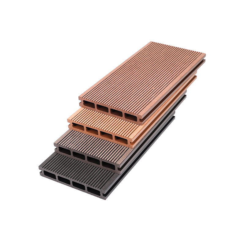
Wood-plastic composites possess a high thermal expansion coefficient. They expand and contract heavily along their length based on ambient temperature fluctuations. Calculating and implementing dynamic spacing prevents the deck from tearing itself apart during seasonal shifts.
A minimum 6.5mm gap is required between butt joints under standard conditions. You must adjust this gap based on the ambient temperature at the exact time of installation. If you install the deck during a cold winter morning, the boards are fully contracted. You must leave a larger gap because the boards will expand significantly in the summer heat. If installing during a summer heatwave, the boards are already at maximum expansion. Leaving a massive gap in summer means the joints will open up drastically in winter. Always consult the manufacturer's specific temperature-to-gap ratio chart for the exact WPC Decking Profiles you are using.
| Ambient Temperature at Installation | Required End-to-End Gap (Butt Joints) | Required Gap Against Fixed Walls |
|---|---|---|
| Below 10°C (50°F) | 8mm - 10mm | 15mm |
| 10°C to 25°C (50°F to 77°F) | 6.5mm - 8mm | 15mm |
| Above 25°C (77°F) | 4mm - 6mm | 15mm |
Never install composite boards tight against a wall. A mandatory 15mm minimum expansion gap is required against all fixed architecture. This includes exterior house walls, masonry planters, and heavy structural posts. Failing to leave this relief gap forces the expanding boards to push against the immovable wall. The kinetic energy has nowhere to go, resulting in the boards buckling upward in the center and ripping the fastener clips out of the joists.
Lateral expansion is less severe than longitudinal expansion, but it still requires management. Hidden fastener clips naturally dictate the 3mm to 6mm side gap required for water runoff, debris clearance, and lateral movement. Do not force boards tightly together sideways to close this gap. Doing so restricts drainage and promotes mold growth in the shadows between the boards. Use a rubber mallet to gently tap the boards into the clips, ensuring they seat fully without over-compressing the gap.
Selecting the correct mechanical fixings secures the deck without crushing the hollow chambers. The geometry of the board dictates the fastening method. You cannot use traditional carpentry techniques on engineered hollow profiles.
Face-screwing is highly discouraged and often strictly prohibited by manufacturers of hollow boards. Driving a screw directly through the top face risks cracking the upper flange. It creates a vertical shaft that allows rainwater to pool directly inside the internal hollow channels. Over time, this water stagnates or freezes, destroying the board from the inside out. Instead, use the manufacturer-approved hidden fastener systems. T-clips slide into the grooved edges of the boards, securing them to the joists while allowing the material to expand and contract linearly. Starter clips secure the first and last boards of the run without requiring face screws.
The most critical framing rule for hollow boards is the requirement for double joisting at every butt joint. When two boards meet end-to-end, each board must rest fully on its own dedicated joist and be secured by its own dedicated clip. Sharing a single 45mm joist at a butt joint forces the clips to sit too close to the very edge of the boards. This leads to edge breakout, clip failure, and boards lifting at the seams. Block out the subframe so that every seam is supported by two parallel joists spaced roughly 10mm apart. This allows water and debris to fall through the gap rather than rotting the timber.
Protecting the vulnerable internal geometry of hollow boards from pests, dirt, and freeze-thaw cycles is vital for long-term durability. Exposed hollow ends trap debris and moisture, accelerating degradation. You must seal the perimeter of the deck to maintain the structural integrity of the core.
Never leave the hollow ends of the deck exposed to the elements. The simplest mitigation involves using proprietary end caps designed specifically for the board's profile. These caps tap into the hollow voids, sealing them off. Apply a small dab of exterior-grade construction adhesive to the prongs of the end cap before tapping it in with a rubber mallet. This prevents the caps from backing out during thermal expansion cycles. Alternatively, installers can use high-grade, color-matched exterior silicone to fill the ends, though this requires meticulous application to look professional.
A more robust and aesthetically pleasing solution is the picture frame border. This involves running solid composite boards or specialized edge profiles around the perimeter of the deck, permanently hiding all hollow ends. Designing a picture frame layout requires complex blocking and subframe modifications.
Installing fascia boards to cover the subframe requires different fastening rules than the main deck. Fascia boards are typically thinner and wider, meaning they expand and contract at different rates. You cannot use hidden clips for fascia. You must drill oversized pilot holes and use dedicated fascia screws. The oversized holes allow the fascia board to move laterally behind the screw head without shearing the fastener or warping the board. Space fascia screws every 300mm, using two screws per vertical interval.
Differentiating handling requirements based on the manufacturing generation of the decking ensures a clean, professional finish. Modern capped composites behave differently under the saw than older, uncapped generations.
Co-extrusion WPC Decking features a protective polymer cap wrapped around the core material. This shield provides superior stain and fade resistance but requires specialized cutting tools. Using a standard, dull framing blade will chip and tear the polymer shell, leaving jagged edges that expose the core to moisture. Always use a high-tooth-count, carbide-tipped saw blade. A 60 to 80-tooth blade on a 10-inch miter saw yields the best results. Cut slowly and let the blade do the work. Do not force the saw through the material, as the friction will melt the polymer cap and create a messy, fused edge.
During the extrusion process, slight color variations can occur between different batches. Before fixing any boards to the joists, unbox the material and sort the boards by batch. Lay them out across the subframe to blend any slight color variations naturally. Check the grain pattern orientation. Most manufacturers stamp an arrow on the edge or inside the channel of the board. Ensure all arrows point in the same direction during installation to maintain visual consistency in how the deck reflects sunlight.
A diagnostic look at post-installation failures reveals that almost all issues stem from ignoring the manufacturer's structural guidelines. Engineering these risks out during the build phase saves thousands in replacement costs and labor.
| Observed Failure | Root Cause | Prevention / Mitigation Strategy |
|---|---|---|
| The "Spongy" Deck | Ignoring strict joist spacing requirements. Spanning hollow boards at 400mm or 450mm guarantees deflection. | Over-engineer the subframe. Stick strictly to 300mm centers for residential applications. Verify load-bearing compliance before laying the first board. |
| Board Buckling | Thermal expansion restriction. Installing boards tight end-to-end during cold weather or failing to leave the 15mm gap against the house wall. | Strict adherence to temperature-adjusted gap charts. Pin the center of long boards with a single face screw (hidden under a plug) to force even expansion in both directions. |
| Internal Freeze Damage | Improper drainage allowing water to pool inside the hollow channels. The water expands during winter freezes, splitting the board. | Ensure the proper 1% to 2% sub-grade slope. Never face-screw the boards. Seal all exposed ends with caps or a picture frame border. |
| Fascia Warping | Screwing fascia boards tightly to the rim joist without oversized pilot holes. | Drill pilot holes 2mm larger than the screw shank. Do not over-tighten the screws; allow the board to float slightly. |
A: For standard residential applications, the maximum joist spacing is typically 300mm to 350mm on center when installing boards perpendicularly. If installing on a 45-degree diagonal, you must reduce this spacing by 30%, bringing it down to 200mm to 250mm on center to prevent deflection.
A: No. Face-screwing hollow composite boards is highly discouraged. It risks cracking the upper surface, voids manufacturer warranties, and creates holes where rainwater can enter and pool inside the hollow channels, leading to internal freeze damage and rot.
A: A minimum expansion gap of 15mm is mandatory where the decking meets any fixed architectural element, such as exterior walls, masonry, or heavy structural posts. This prevents the boards from buckling upward as they expand in hot weather.
A: Yes. Leaving hollow ends exposed allows moisture, dirt, and pests to enter the internal channels. You should seal the ends using proprietary end caps, color-matched exterior silicone, or by designing a solid picture frame border around the deck perimeter.
A: Double joisting ensures that each board end at a butt joint rests fully on its own joist and is secured by its own independent hidden fastener clip. Sharing a single joist forces clips too close to the board edge, causing the material to break out and fail.
A: If water enters the hollow channels through face-screw holes or exposed ends, it can stagnate and promote internal mold. In colder climates, trapped water will freeze and expand, which can split the composite board open from the inside out.


